DOSING PUMP CONTROLLER

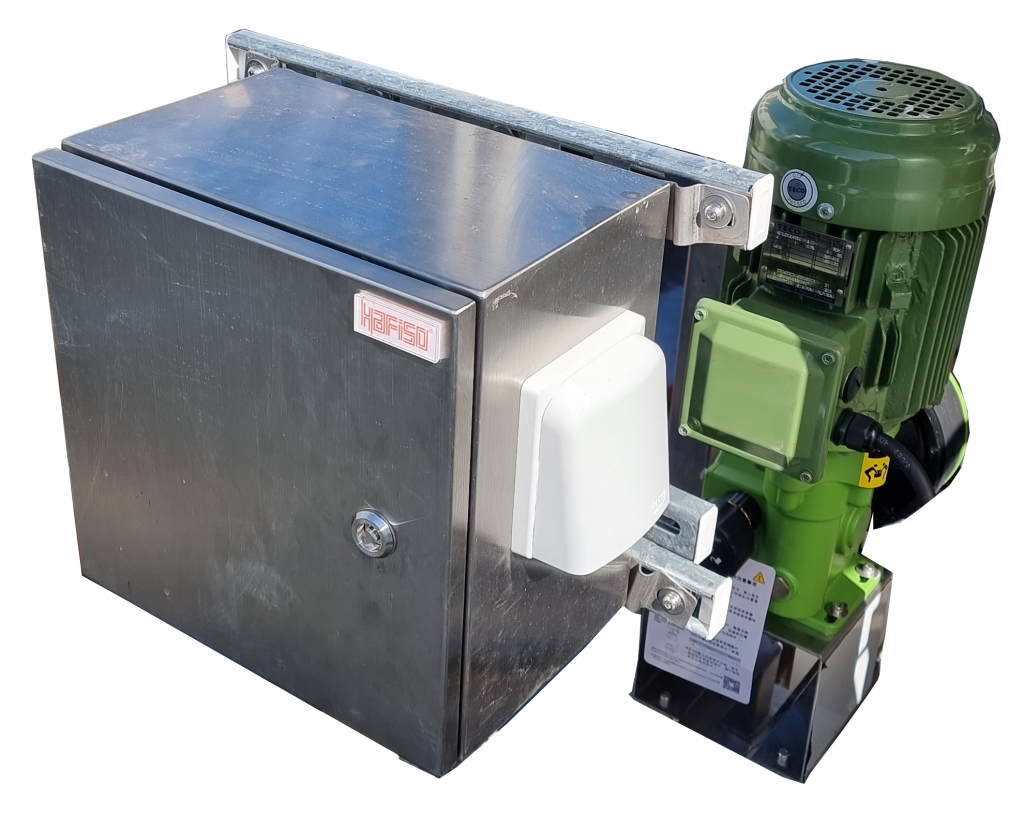
A dosing pump controller with VFD (Variable Frequency Drive), alarm, and status feedback is an advanced system designed to accurately control the dosing process while providing essential monitoring and feedback capabilities.
The controller acts as the central unit that interfaces with the dosing pump and other peripheral devices. It incorporates a VFD, which allows precise control of the pump’s speed and flow rate by adjusting the frequency of the electrical supply. This ensures accurate dosing and enables the system to adapt to varying process requirements.
The controller also features an alarm system that monitors critical parameters such as pump failure, low chemical levels, or abnormal operating conditions. In case of any deviations or issues, the alarm triggers an alert, notifying operators of the problem, and preventing any potential damage or disruption to the process.
Furthermore, the status feedback functionality provides real-time information about the pump’s performance and operating conditions. This feedback includes parameters like flow rate, pressure, motor speed, and power consumption. Operators can monitor this information through a user-friendly interface, enabling them to make informed decisions, optimize dosing processes, and detect any abnormalities or inefficiencies.
Overall, the dosing pump controller with VFD, alarm, and status feedback combines precise dosing control, comprehensive monitoring, and timely alerts to ensure accurate and reliable chemical dosing while maintaining optimal process conditions.
ROBOT CONTROLLER

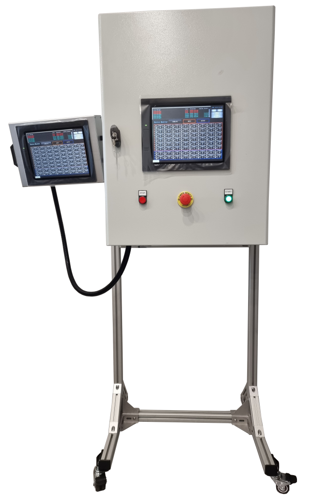
An automation controller that includes a Programmable Logic Controller (PLC) and a Human-Machine Interface (HMI) is a common setup in industrial automation systems. Let’s break down the components and their functions:
- Programmable Logic Controller (PLC):
-
- The PLC is a digital computer designed to control and automate various industrial processes. It consists of a central processing unit (CPU), input/output (I/O) modules, and memory.
- The CPU executes the program logic stored in its memory and performs real-time monitoring and control of connected devices and equipment.
- The I/O modules interface with the external world, allowing the PLC to receive input signals (sensors, switches, etc.) and send output signals (actuators, motors, valves, etc.) to control the connected machinery.
- The PLC programming language is typically ladder logic or a variation of it, which is easy to understand for automation engineers.
- Human-Machine Interface (HMI):
- The HMI serves as the interface between the human operator and the automation system. It allows operators to monitor the process, control parameters, and interact with the system.
- The HMI typically consists of a graphical display (touchscreen or monitor) that presents real-time data, system status, alarms, and other information in a user-friendly format.
- Operators can use the HMI to input commands, set operating parameters, and initiate actions.
- HMI software enables the design of custom user interfaces with various elements like buttons, switches, charts, and trends.
The automation controller integrates these two components to form a cohesive system. The PLC performs the logic control and data processing tasks, while the HMI provides the operator interface and visualization capabilities.
The PLC and HMI communicate with each other through a communication protocol, such as Ethernet/IP, Modbus, or OPC (OLE for Process Control). This allows the HMI to retrieve real-time data from the PLC, display it to the operator, and send control commands back to the PLC.
By combining a PLC and HMI, industrial automation systems can achieve efficient control, monitoring, and visualization of processes, leading to improved productivity, reliability, and ease of operation.
